Cessna 02 Cockpit — Looking Slightly Askew
.jpg)
Having decided to build a proper panel in the style of the Cessna 02, I began serious homework duties.
If you wanted to build a 172 this would be easy, peasy. You'll just download an accurate panel template created by someone else and start work. However, if you really wanted to build something altogether more interesting, then you'd be faced with many dilemmas, not least of which would be attempting to fathom as accurately as possible, the panel width, height and shape.
If you look hard you can see the 02 instrument panel is really three separate panels. There's the main panel, a shock panel carrying the main flight instruments which is set about half an inch clear of the main panel on the pilot's side and a further shock panel on top of that that carries the rather delicate vacuum instruments.
To accurately assess such a panel's true dimensions from photographs you must have something of known dimension to work from, and for this I used the only measurement possible — that of the standard Cessna large instruments which have 3 1/4 inch bezel width.
This dimension is useful, but you will find very few pictures of cockpits that are taken head on and I could not find one anywhere. For some reason the photographer always takes his pictures of a cockpit from an angle and his skewed viewpoint means that you cannot easily gauge the true panel dimensions by using multiples of the known measurement of the bezels.
I imagined that it was about 3 inches wider than my maximum possible cockpit width (41-inches) and somewhere around 10 inches in height, so if these initial calculations were correct then I knew that I must scale down a little to fit.
This would mean that I would also be forced to scale down the instruments too. Maybe three-inch bezels rather than 3-1/4...
This worried me endlessly.

Finally, I found something of an answer to these dimensional dilemmas.
Trawling through image search results for "Cessna 02/337" a little revelation was eventually spotted far into the back pages, and one that could so easily have been missed.
This was most accurate plan view that I had yet found...
It was supplied by a remote control model maker!
And though it was not to be completely trusted, it was good enough in the absence of anything better and certainly more reliable than any photograph.

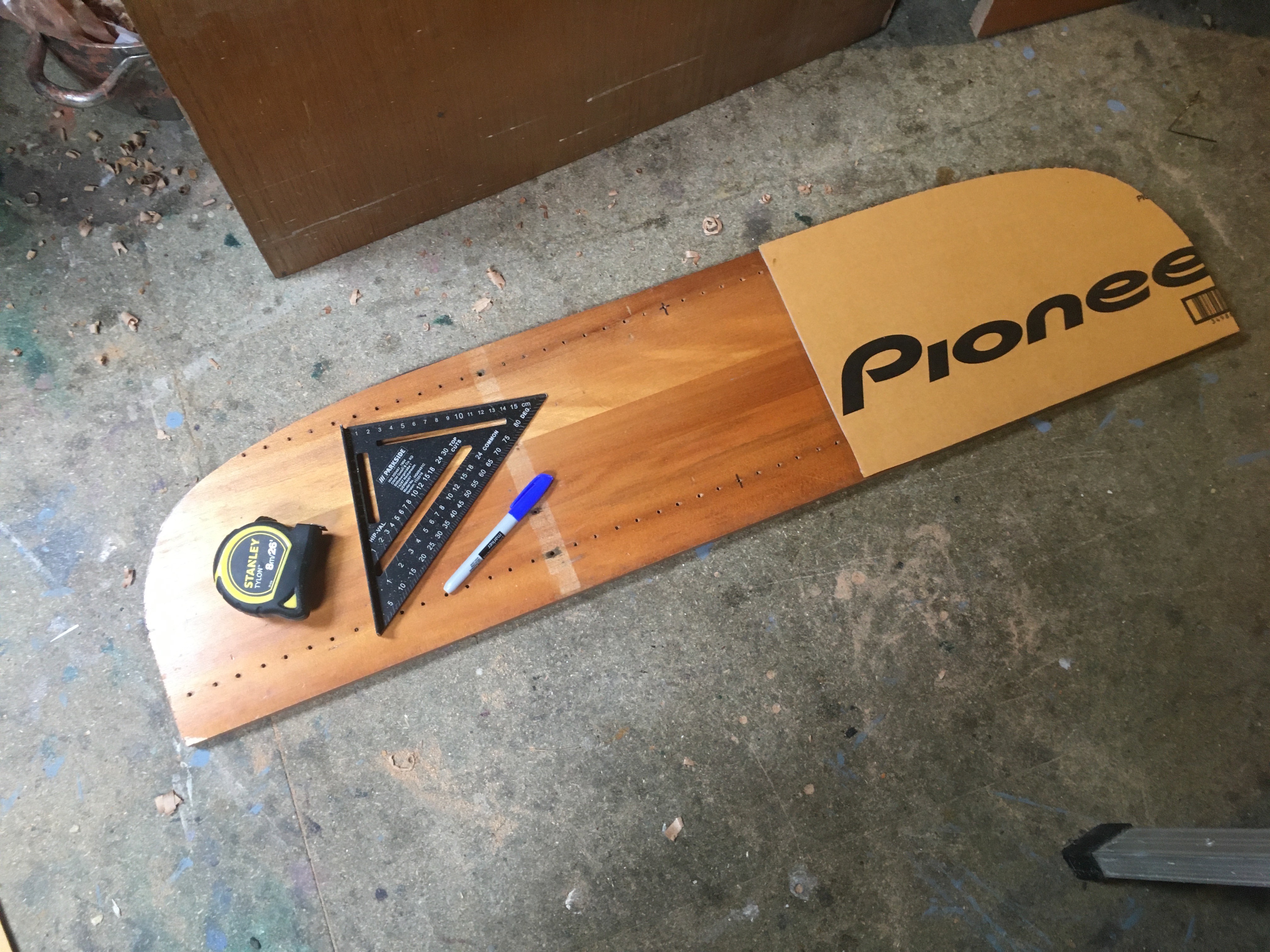
With something to go on, I began work with a high quality pine plank sourced from a set of old bookshelves. The curved top was created by means of a sheet of paper that was placed on the computer screen in order to trace the outline of the plan.
This tracing was simply eyeballed and drawn onto the plank as best I could.


Comments
Post a Comment