Cessna 02 Cockpit — One Crucial Inch of Difference

Months have passed by since I put the 02 project to bed for a well-earned Summer nap.
It's woken up now...
And is as grumpy as hell!
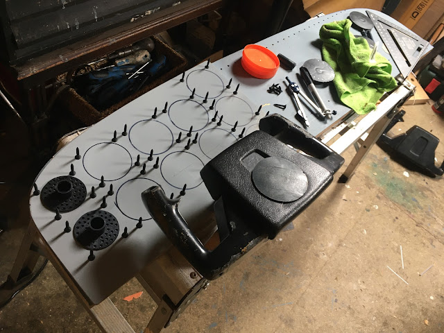
I set to work ~
By offering up the 02 shock panel to the already established flight sim in the corner of the room, I initially thought that it was not quite tall enough.
So, I made a drawing on paper of the panel and its instruments with slightly taller proportions...

Although the instruments of the real 02 panel are very crowded together, alas, mine in this drawing were just too close to each other for comfort.
Another drawing was made. ~
This time I made sure that every instrument had an eight-of-an-inch clearance from it's immediate neighbours and this was better. but still not quite right...
 |
And then, just as I was getting a little desperate with all this faffing about with wood, pencils, rulers and paper, a possible solution to all my problems finally and thankfully arrived on my doorstep!
Quite by happen-chance, I'd stumbled over the original flight manual (in PDF format) for the USAF SERIES 02-A AIRCRAFT during yet another of my drags through the mire of the Internet.
Needless to say, I read it cover to cover and over and over!

What was really special though, was that the manual contained a series of beautifully drawn illustrations of every important cabin detail.
These immediately became my most trustworthy sources of hard information because it's clear to me that a highly skilled draftsman created them. One who would have quite particular about every small detail including making sure that all proportional relationships were drawn as accurately as possible ~

The official figure for cabin width, but not instrument panel, is 42 inches.
I'd established that truth beyond any possible doubt, but...
I am limited to 41 inches.
Oh shit!
What matters here is quite how that width was measured. Was it from interior wall to wall, did it include the insulating padding, or indeed, was it an external measurement?
I set to task to find this out by using a pair of dividers to accurately measure both the height and width of the panel, because these had become seriously important things to know, and to know, exactly.
I printed a paper copy of the 02 manual illustration...
By setting the dividers to the width of the only object drawn that could be absolutely trusted — one of the large instruments at 3-1/4 inches — they were then danced across the print, top to bottom and edge to edge.
The full height, which had troubled me so, was found to be just under 11-1/2 inches whereas I had estimated it as being an inch less at 10-1/2. My shock panel was probably correct after all but the main panel below should have been made one-inch deeper.
Easily sorted! Add an extra inch of wood!
And then, the really important dimension.
The dividers skipped 13.8 times across the panel, edge to edge ~
13.8 x 3.25 = 44.85 inches in width.
Such a figure did not agree with the official 42 inches nor did it agree with my 41 inch limitation.
Drat!
However, a small detail had eluded me briefly.
And then I remembered what it was!
You'll see in the 02 manual illustration above that there are small 'wings' of metal each side of the instrument panel. With reference to the photo below of an old and decrepit warbird, you'll see that these wings fitted neatly into the side walls below the front window...

Combined, these two 'wings' make one hell of a difference, for they add up to about three-inches in total.
Subtract that from 44.85 and we get 41.85. And so it seems that my panel is actually about an inch short of ideal and the official 42 inches was indeed an internal measurement and one that was measured including the padding.
So, it's really not the significant problem that I thought it might be. It can be easily dealt with, I'm sure.
Back to work!.

Comments
Post a Comment